I’ve fiddled around with Arduino-based microcontrollers for some time, but never wrote about it. I thought it’d be fun to show off a silly thing I made recently because I think it’s really cool, but also kind of pointless, so maybe sharing it with the world can be its actual reason for existing… Then I can take it apart and reuse its guts.
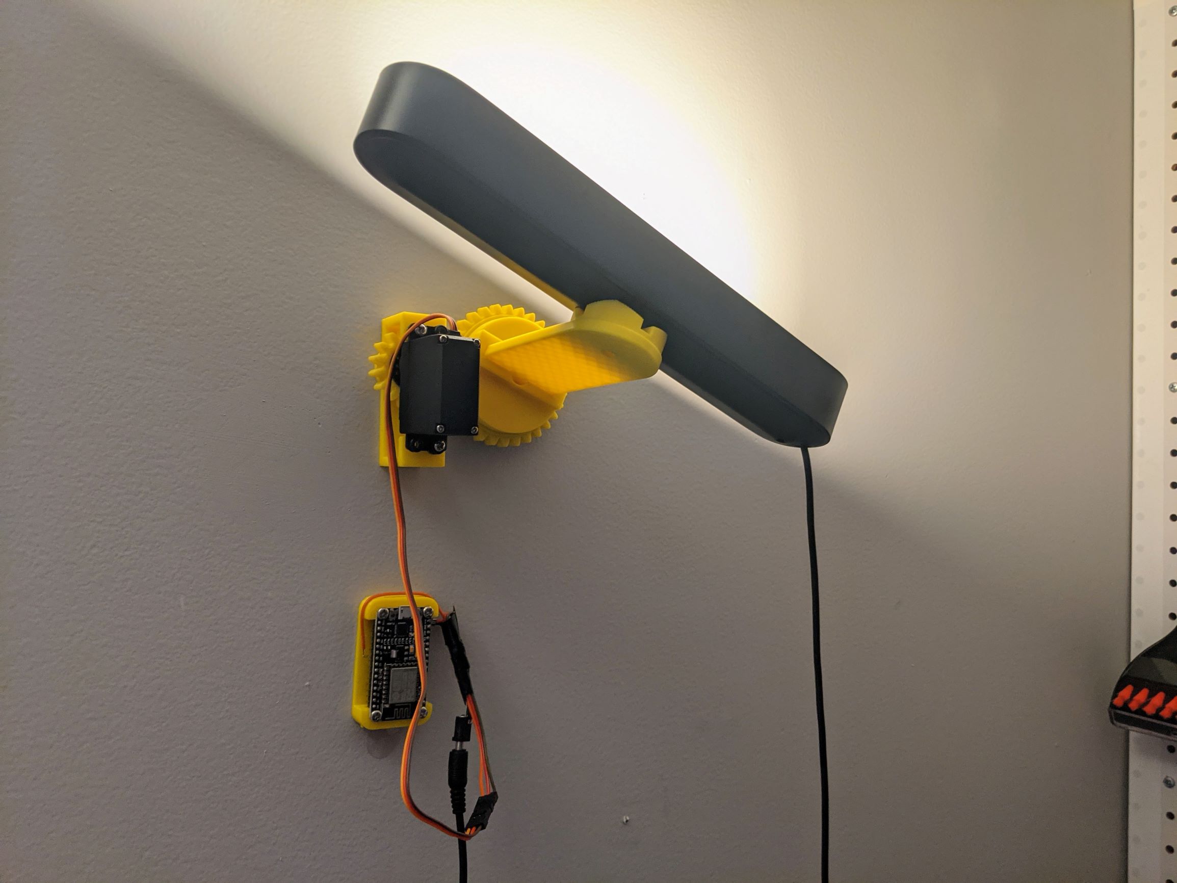
I present, the network-controlled swiveling wall lamp.
There’s a crappy video and parts list at the end, if you want to scroll past all of the (shockingly impressive) how-it-works stuff to find it.
OK so what exactly is this thing? The lamp itself is a Philips Hue Play White & Color Ambiance Smart LED Bar Light of which I have a few in my home office. Sticker shock warning: they’re not giving these things away. They’re really nice, though.
NB: you need to buy the “base kit” to get the power supply, which can power three bars, then you can buy single bars as an “extension” item… That is, unless you’re comfortable cutting the wires and soldering smaller barrel plugs onto them, then you can use any 24V 1A adapter you want. But who would do that?? 😏
The yellow thing it’s connected to is a 3D-printed remote swivel assembly that uses a MG995 “micro” servo to turn the lamp left and right on that big gear you can see behind it.
Inside that big gear is a 40mm deep groove ball bearing that allows the geared assembly to rotate with very little effort, although the gear ratio between the servo-driven gear and the larger gear is such that the bearing may not have been strictly necessary, but it definitely makes the rotation part quieter.
I say “rotation part” because the servo itself is pretty noisy, and is one of the downsides of this whole project. I think a stepper motor would provide a better experience, but they’re expensive and the accuracy is totally unnecessary.
Anyway I’m on a tangent, let’s get into how this thing came together and how it works.
The engineering part
I started with some sketches. Which I can’t find. So trust me, I did actual sketches on paper with a pencil to get an idea of how I wanted this thing to work.
From there, I moved into Fusion 360 to model the yellow part. I had previously designed and printed mounting arms for these light bars before, so I knew I could just copy that portion, but I had to learn how to model spur gears, figure out what size gears to use, and create the structure that would hold the motor itself.
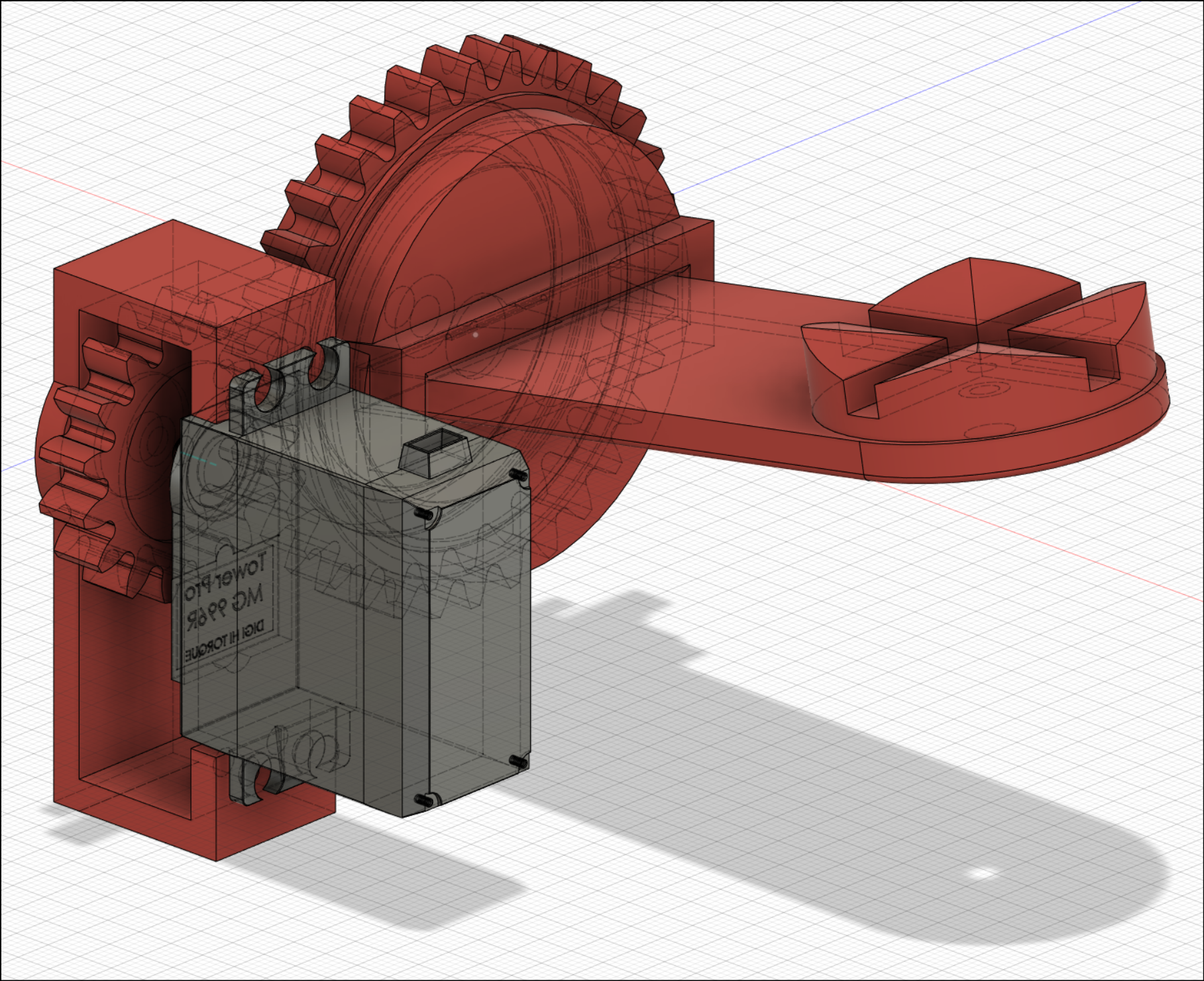
This part was the hardest, although the gears and motor aligned perfectly on the first try. What I had some trouble with was the mount for the motor to its drive gear, which took a couple tries before I got the depth right.
As with all 3D printed parts, they took forever to print, so this whole portion of the project took a couple of days, working on it an hour or two at a time in between work and chasing my kid around, or during the hours I deprive myself of necessary sleep.
Protip: when you’re modeling a part that will accept a retail component, like a servo motor, hop on grabcad.com and see if you can find a model of it there. Most of these hobbyist parts like motors and microcontroller boards are on there. This saves you the time of modeling it yourself, and gives you a much better idea of how everything will fit together.
While no two of these motors are ever exactly the same in design, all of the major dimensions were spot on, which saved me a ton of trial and error and/or tricky caliper situations.
Sorry I don’t have any photos of assembly.
The 40mm (inner diameter, or “ID”) ball bearing is a friction fit into the back of the large gear, and it worked on the first try, although I had to use pliers to get it to seat in there. Remember, PLA shrinks a tiny bit when it dries, so your diameters may end up ever so slightly smaller than designed (on top of any dimensional slop caused by your printer’s accuracy).
The software part
I wanted to be able to drive this thing remotely. Kind of the point of it is being able to move it without reaching over there. I decided to go with an ESP8266 board, because it’s programmable in the Arduino IDE and has on-board WiFi.
I like these HiLetgo ESP8266 NodeMCU boards. NodeMCU is a whole thing you can go look up, there are other ways to program them, but I’ve only ever used the Arduino IDE and Arduino C-derived language that I’m familiar with. They pretty much work straight away, you just need to install the ESP8266 libraries (instructions on the Amazon page, but also see ESP8266 on Github) and find some copypasta for connecting to WiFi (which I will provide momentarily).
That gets you connected to WiFi, but how do you remotely control the lamp’s position? There are plenty of options, but I didn’t want to do something complicated like try to run a small web server or use some low-level network protocol like Telnet. I wanted a method that would give me options for how to send the commands. I decided to use MQTT.
If you haven’t heard of MQTT, it’s an open standard pub/sub TCP/IP messaging protocol “that provides ordered, lossless, bi-directional connections.” MQTT is all the rage in homebrew home automation systems because servers and clients are easy to stand up, come in all platform flavors, and the protocol is lightweight and straightforward to use.
This choice was made easier for me by the fact that I already run an MQTT server, which I won’t get into here, but if you’re interested in all that perhaps I could do another post on it, just ask in the comments.
There is a readily available MQTT client library for Arduino, so this is all rather simple to get up and running, you just have to get the libraries installed and, once again, find the correct copypasta incantations to place in your code to make it all work.
To save you the trouble, here is my (admittedly pretty terrible) code:
The basic concept is that the controller connects to WiFi as soon as it turns
on, and then it subscribes to a topic called lightbar/1/cmd, on which it
listens for new messages.
The messages are expected to be integers, and those integers represent a location that the light should move to, in degrees between 0 and 180, because that’s how servo motors work (or, how this one works, anyway; you can get 360-degree servos but they’re less common).
So when the controller receives an integer on lightbar/1/cmd, it figures out
which direction to move the motor to get to that location and tells the motor to
move that distance. There are some contortions required due to how servo motors
work, which is all pretty apparent in the code, so I won’t go into detail
here.
For fun, it also publishes what it’s doing to lightbar/1/stat so another
client can listen on that to see if the program is acknowledging the messages.
Nice work!
Hey thanks.
But seriously, this project taught me a lot and was super satisfying to accomplish, but it turned out to be among the most useless things I’ve ever made. Rotating the light back and forth has almost no appreciable effect on the lighting of the room, believe it or not, and so in spite of being like really super cool to show off, it’s totally pointless.
On top of that, it’s kind of loud, which might be because this servo from Amazon was (relatively) cheap, but most RC servos make this sort of buzzing sound so I think it’s a function of how they work and it’s unlikely I’ll find a quiet one within my budget (not to mention that I no longer care).
Here, listen for yourself.
Parts and stuff
Want to make something like this? That’s awesome, you’re going to have a ton of fun. Here are the parts I bought for this project:
- Philips Hue Play Black & Color Smart Light, 2 Pack Base Kit
- Philips Hue Play Bar Light, Extension
- HiLetgo ESP8266 microcontroller boards
- uxcell 6808-2RS Deep Groove Ball Bearings 40mm ID 52mm OD
- Seamuing Micro Servo Motor MG995 (4PCS)
- Ybee SG90 Micro Servo (10PCS); I tried to use one of these at first, but it didn’t have enough torque. These are much quieter and you can control them with the exact same code. Highly recommend for your low-torque applications.
Disclosure: if you follow the links above, Amazon kicks me a microscopic percentage of the sale. Translation: pleeeeease click my links.
If you do end up making something based on literally any of this, I want to know about it! For real, you can post a comment here or DM me on Twitter, show me what you got!